
 |
||
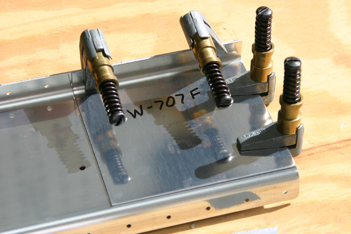
| Here is where the fun begins for the rear spar of the right wing! You may have noticed the agonizingly slow pace of construction...at this rate I'll be done by 2010 (well, maybe!) Its hard to find time for the shop nowadays, so bear with me. Anyway the rear isn't that hard to build. Here is the outboard edge of the spar with the doubler plate cleco-clamped into place for drilling. Later on the aileron hinge brackets will attach here so this doubler plate adds some strength. |
||
 |
||
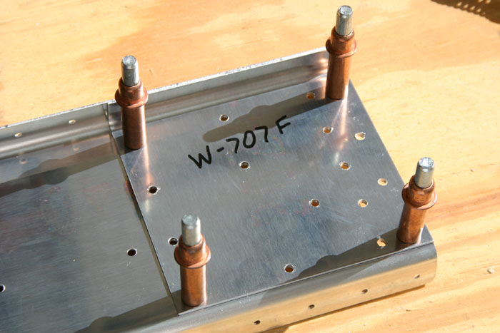
| The spar is pre-punched and the doubler is not. So all you do is flip the assembly over and back-drill through the pre-punched holes into the doubler and you now have a matched pair for riveting. Here it is cleco'd together. | ||
 |
||
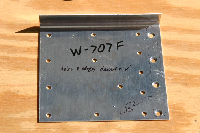
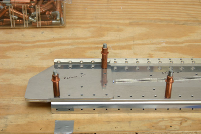
| Here is another shot of the outboard doubler plate. Notice that I have countersunk the outboard holes (right hand of photo). The reason is that later on the aileron bracket will sit over this doubler here and so basically this doubler is attached with these holes to the rear spar with flush rivets so that when I put the aileron bracket on it can sit flush. Its kinda hard to visualize but I think you get the idea. | ||
 |
||
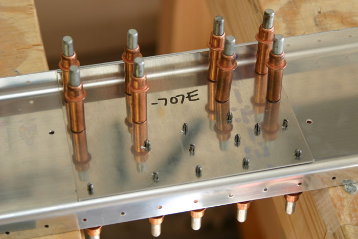
| Here is approximately the mid-point of the rear spar. This doubler plate accepts some brackets for the flaps and ailerons, which is why it is needed. You do the same job as before...cleco the doubler on and match drill the holes using the pre-punched holes in the spar. | ||
 |
||
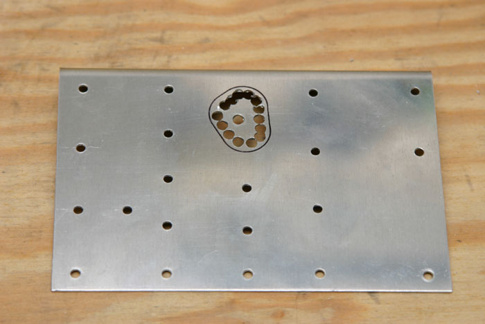
| Now this was kinda fun! You take that doubler that you just drilled and begin to cut out a large oblong hole nar the top. This is to make room for the aileron pushrod that will (one day!) come though here and push the aileron up and down. I began by tracing the outline of the hole using the pre-cutout hole in the spar (easy!). Next, I drilled several holes near the edge as shown above to cut out most of the material. | ||
 |
||
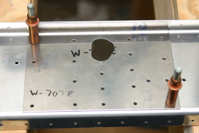
| After that it is just a matter of using a die grinder, sandpaper, and a dremel to finish the cutout. Notice the nice fit with the pre-cutout hole that came in the spar. Cool! | ||
 |
||
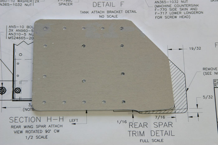
| Ok, now moving a bit more inboard here is a pic of a much thicker doubler plate that goes on the inboard section of the spar, right where the rear spar of the right wing will one day attach to the fuselage. This piece originally came larger (look at the dwg), and I cut it down to the proper size and polished it. This is where my bandsaw has come in extremely handy! I definitely recommend one....it only cost $70 or so and it saves mucho time. | ||
 |
||
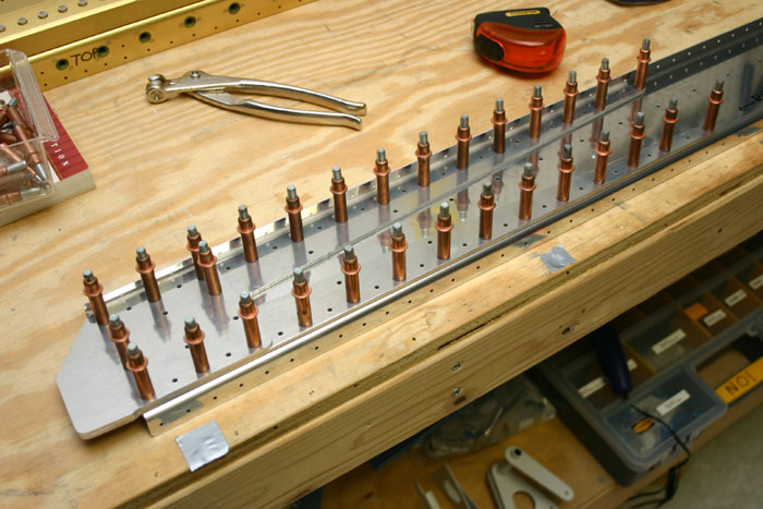
| Here is a shot of the inboard section of the spar. Its kind of hard to see, but there are 2 doublers here. One very long one (about 2 foot, "V" shaped), and on top of that is the shorter one you saw earler. Here they are cleco'd in place for match drilling with the underlying spar. | ||
 |
||
| And her is a much better picture of the inboard section. Notice that I have also (per the directions) dimpled the uppermost holes in the spar flange because this would be very difficult to do after this assy is riveted together. | ||
 |
||
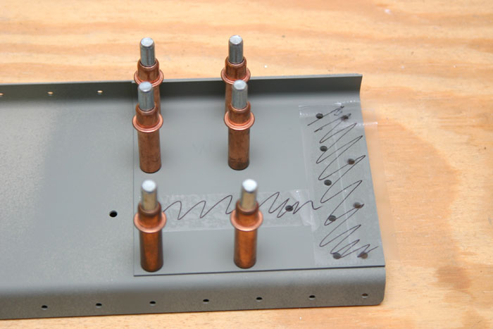
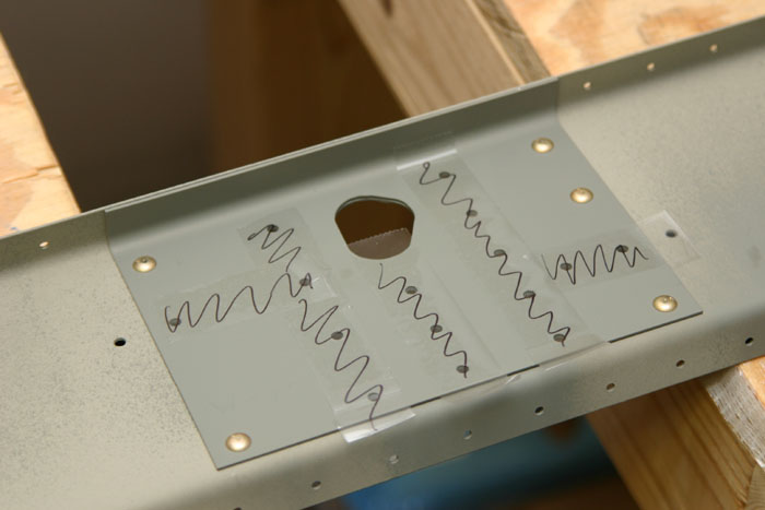
| Now the real fun begins. I primed the components and I'm ready to rivet them together. The only catch is that many of these holes shouldn't be riveted right now because they need to be riveted in assembly with other things like ribs, hinge brackets, etc. So I put tape over the holes that so not get a rivet just yet. | ||
 |
||
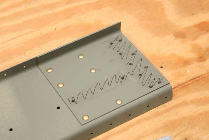
| And here it is riveted on! | ||
 |
||
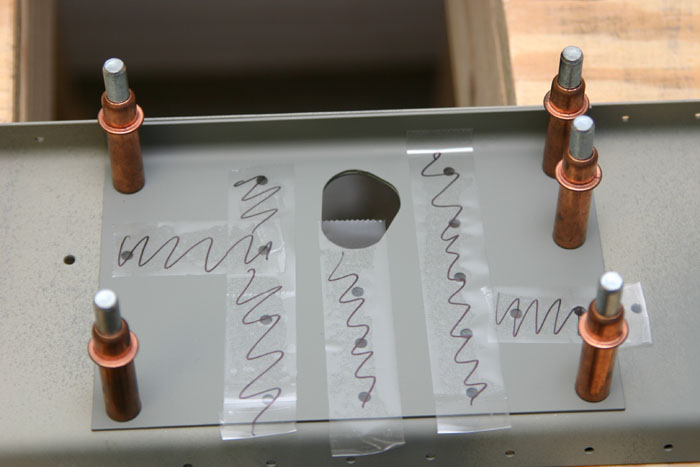
| Next up is the center doubler plate all cleco'd on with tape over the holes that don't get riveted. You might be wondering what would happen if you accidently riveted one of these holes? Well you'd need to break out your trusty drill and drill out the rivets! | ||
 |
||
| Rivets in place! | ||
 |
||
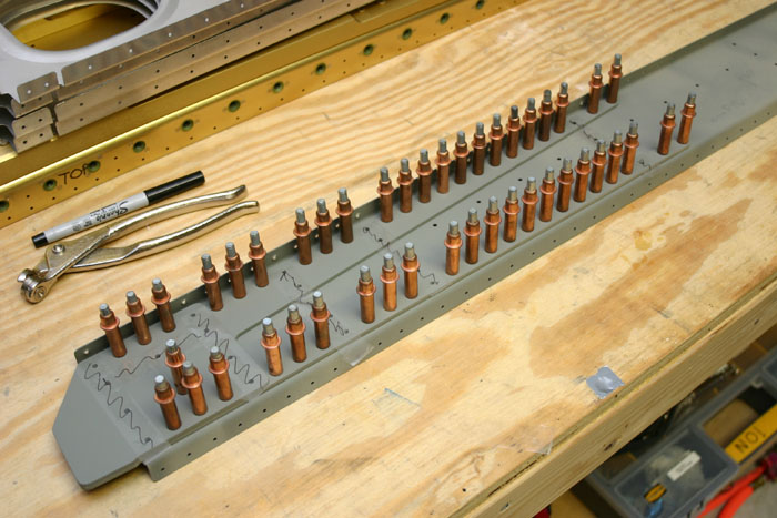
| And here is the inboard section. Notice that I have a cleco in every hole that should get a rivet. This is a tip I picked up from the Ordnorf videos (highly recommended). This way you should remove a cleco for every rivet you set. Pretty hard to screw up if you do this. | ||
 |
||
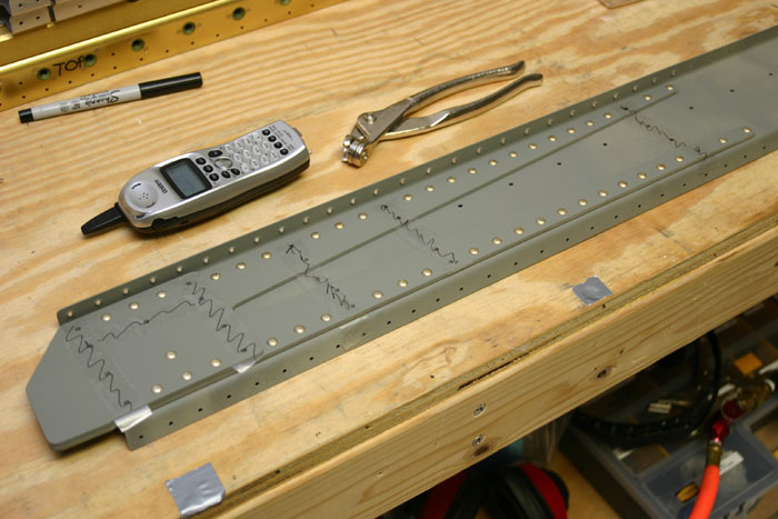
| And here is the inboard section. The rear spar assembly is riveted together! Next up is preparing the wing ribs and match-drilling the skins on! | ||