
|
2/03/04
|
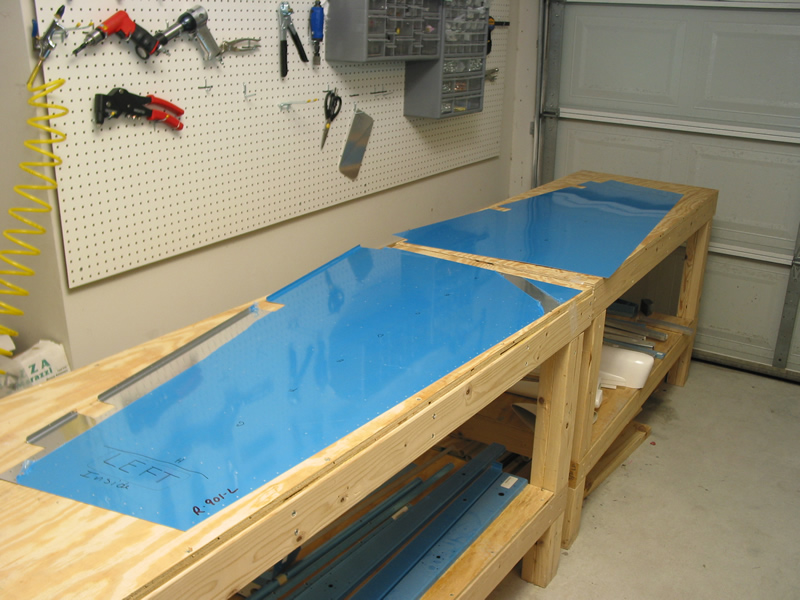 |
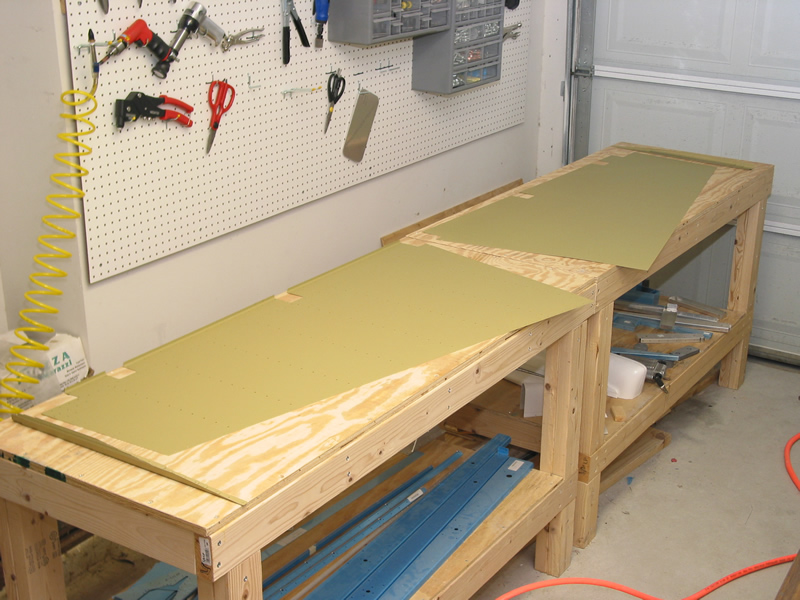
Here is a pic of the rudder skins. The rudder skin is much thinner than the skins of the horizontal and vertical stabilizer....but the biggest difference is that it comes two pieces instead of one. If you can image taking both ends and lifting up towards the ceiling that is how this thing will go together. |
|
|
|
|||
|
2/04/04
(1 Hrs) |
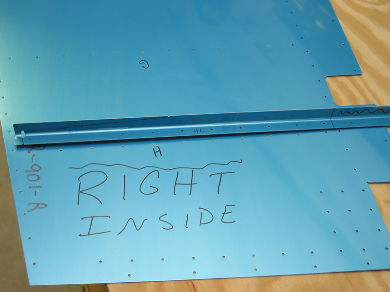 |
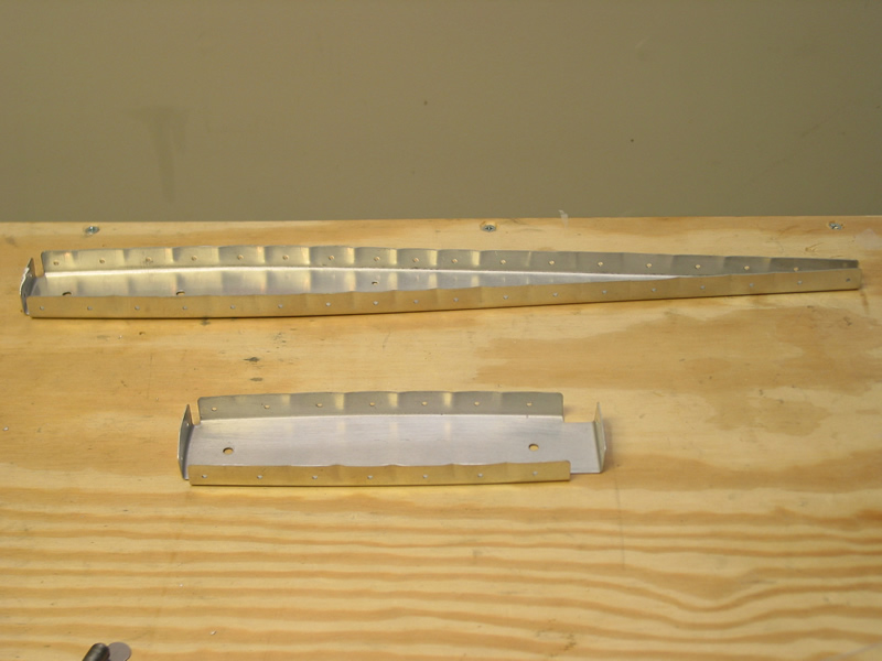
Instead
of ribs the rudder has what are called 'stiffeners' to make it rigid.
The stiffeners are made from aluminum angle. The angle has notches
in it to tell you how to cut the thing. Note that I have drawn a line
that I will use to guide my cut. There is a taper because the rear
most part of the stiffener sits where the two halves of the rudder
come together so this taper allows the skins to meet without interference. |
|
|
2/06/04 |
 |
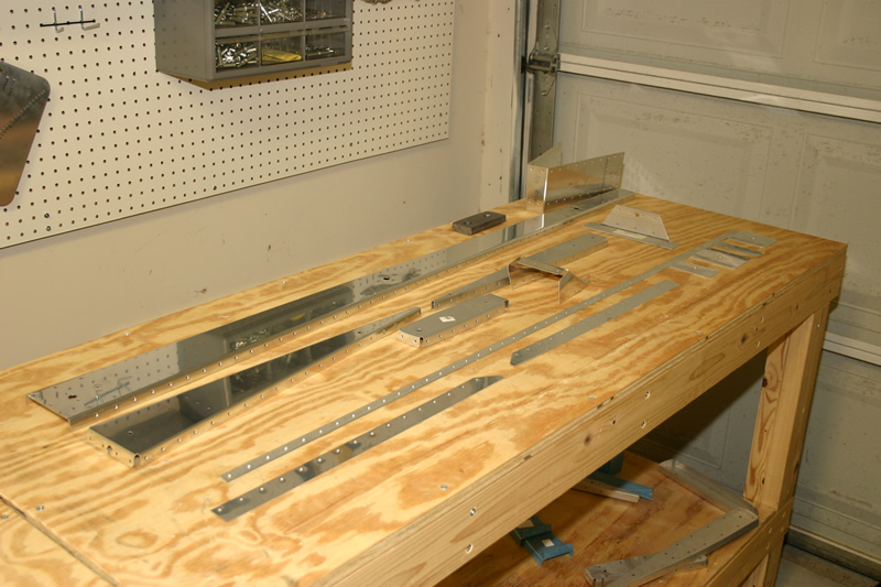
I spent some time carefully trimming the rudder stiffeners to the proper size and taper angle. I began by using my aviation snips to remove the bulk then finished the job in my bench grinder with scotchbrite wheel. | |
 |
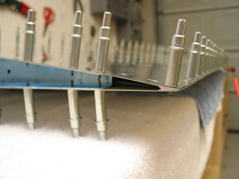
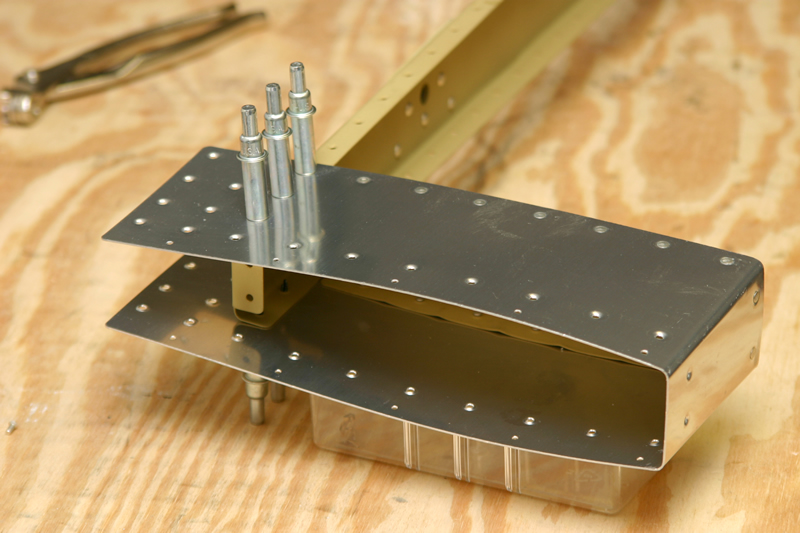
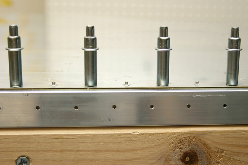
Here is a close up of the inside of the rudder trailing edge with the stiffeners cleco'd into place. Notice that the end of the taper is quite close to the trailing edge of the rudder. Care needs to be taken when back-riveting the last rivet here...you need to set the rivet enough so that it won't hit the other skin when you do the final assembly. | ||
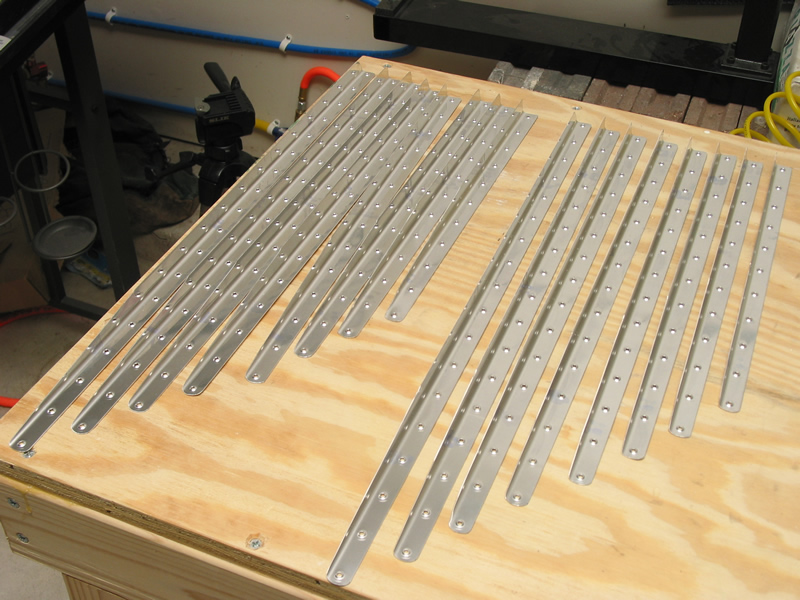 |
Here are all 16 stiffeners on the workbench just ready to be primed. | ||
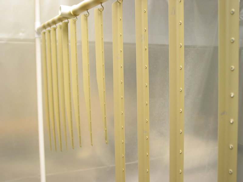 |
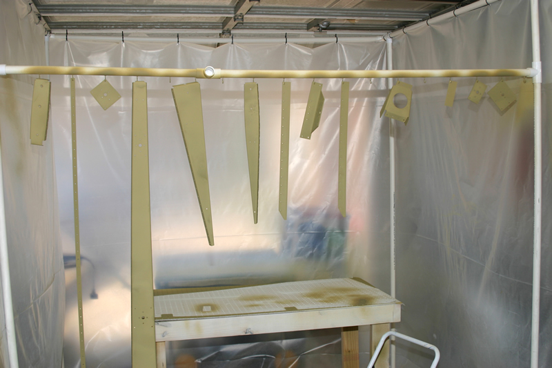
I hung all 16 stiffeners in my booth and primed them all at one time. I switched to a new primer called Dupont Variprime. This stuff rocks. It is self etching and dries very fast. All you do is clean the metal with a degreaser then shoot the primer on. No need to scrub with scotchbrite! It etches as it cures and it is fully dry in a few hours. | ||
|
2/11/04 |
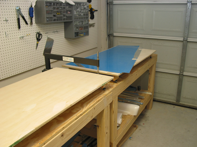 |
Finally decided to build a dimple table. I got this idea from some builders on the net and so far it is working great. Basically you just get a flat piece of plywood, attach four legs then put adjustable levels under each leg. In this way you can raise and lower the table height easily and can make it flush with your C-frame tool. | |
 |
Just another shot to show you my dimple table setup. | ||
 |
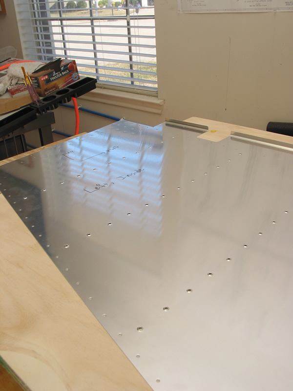
Here I am dimpling the right hand rudder skin. The rudder skin is quite thin and it doesn't take as much force to dimple it as compared with the HS or VS. | ||
|
2/15/04
(3 Hrs) |
 |
Here I have finished dimpling the left hand rudder skin. | |
 |
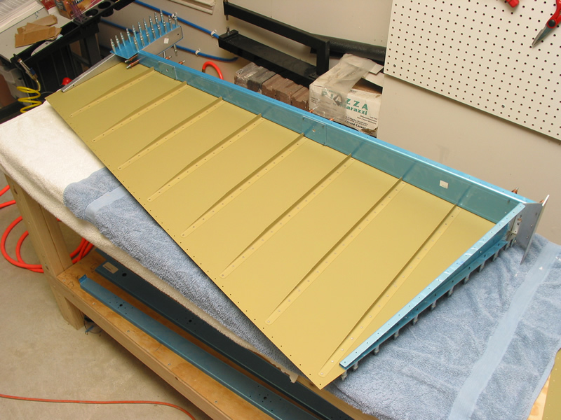
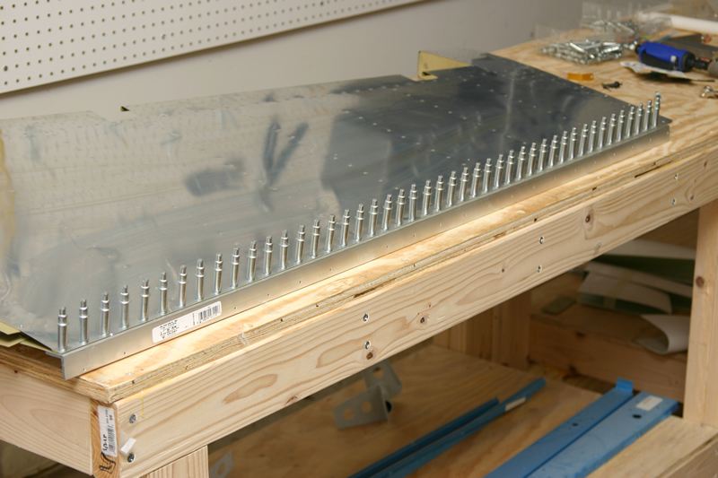
These are the rudder skins primed and ready to be back riveted to the stiffeners. | ||
|
2/17/04
(2 Hrs) |
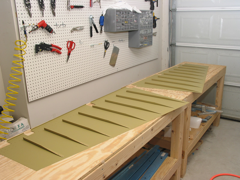 |
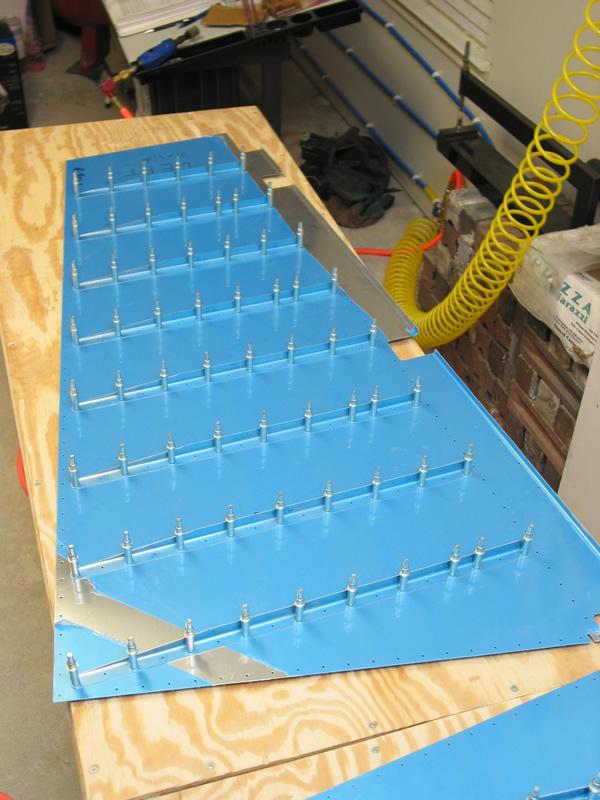
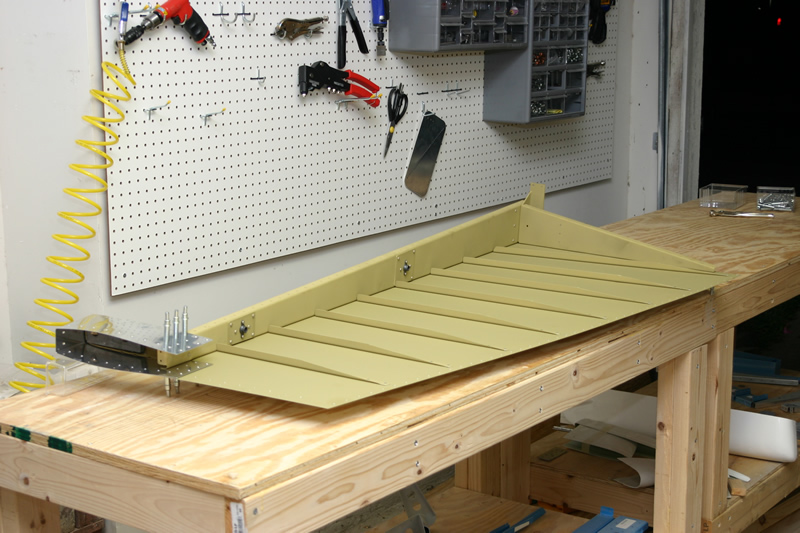
Here are the skins with the stiffeners riveted into place. Back riveting is so much easier than "regular" riveting! | |
 |
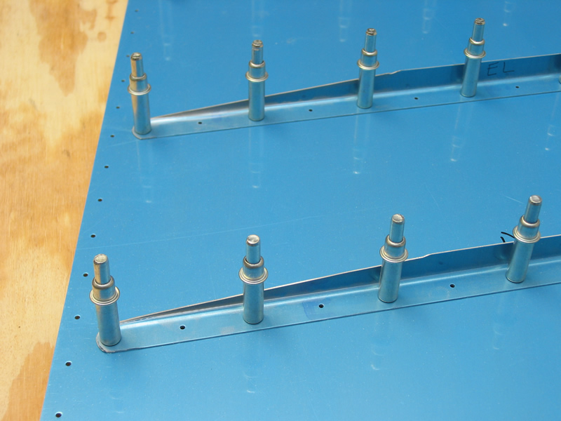
Close up of a typical rudder stiffener riveted into place. Notice the taper on the trailing end to allow for the other skin to meet the edge without interference. | ||
|
2/23/04
(2.5 Hrs) |
 |
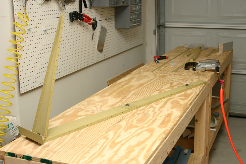
This is the forward spare and lower rib of the rudder skeleton. The aluminum object at the lower end of the assembly is called the rudder horn. Later on the control cables will attach here to pull the rudder left or right. | |
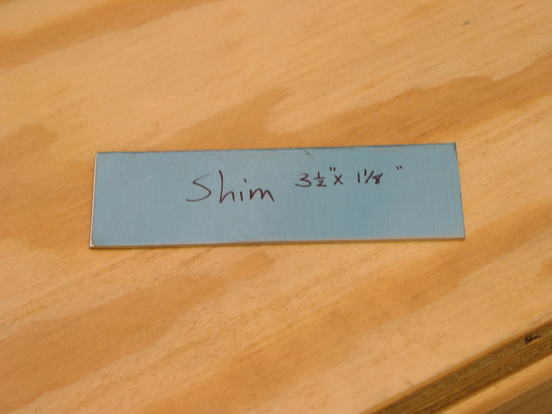 |
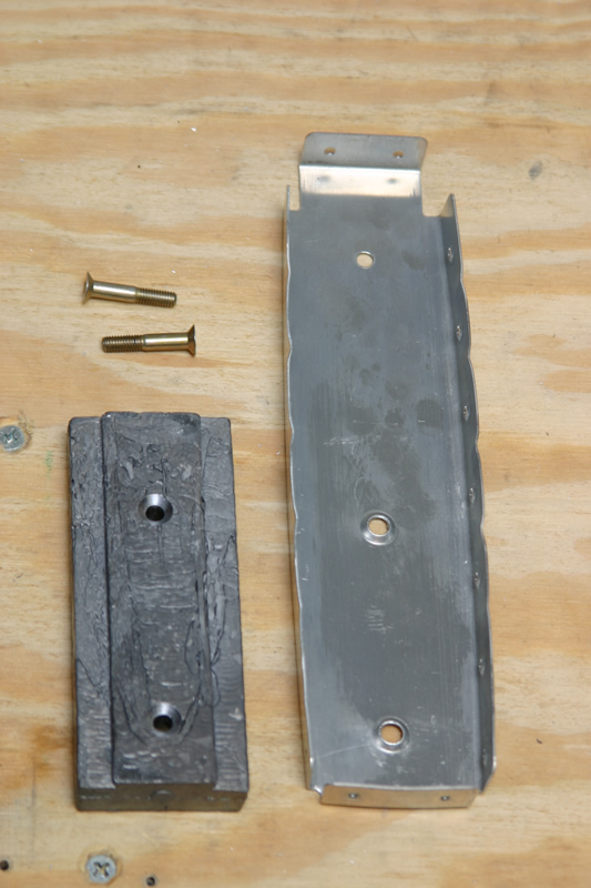
This is a small shim you need to construct to attach the horn to the lower rib. | ||
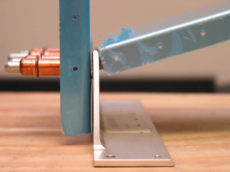 |
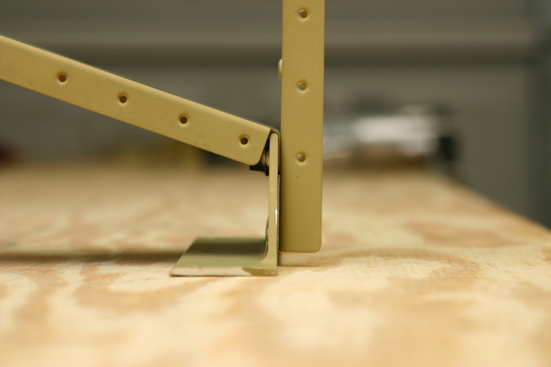
This is a close up profile view of how the horn attaches to the forward spar and the lower rib. Notice the shim that fits between the horn and the forward spar. I thought this particular assembly was a little hard to see in the drawing...this picture says it all. | ||
 |
Here I have fluted the top rib and the counterweight rib. | ||
 |
Here the top rib and the counterweight rib are cleco'd to the spar along with the counterweight skin. Later a counterweight will be permanently attached inside this assembly to help balance the rudder "feel". | ||
|
2/24/04
(2 Hrs) |
 |
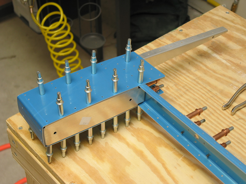
Here I have started assembling the rudder skin and spar in preparation to match drill the holes to final size. | |
 |
And the rudder is cleco'd together and match drilled to final size. | ||
 |
Here is the trailing edge of the rudder. Notice the wedge in place to give the edge some support. This taper is the reason that the stiffeners needed to be tapered in the beginning. | ||
 |
Since the horn will take the load of pushing on the rudder, it has a brace, called cleverly enough, the horn brace. It basically attaches to the rudder horn on one side and to the underside of the lower rib. | ||
 |
Here is another pic of the horn brace from the underside of the assembly. | ||
|
3/06/04
(1 Hrs) |
 |
Next I have fabricated and attached two small strips of skin to each side of the rudder. You use the cleco clamps to hold the strips in place and match drill with the skin holes. Later these pieces will be riveted in place and will be used to attached the rudder bottom (fiberglass piece). | |
|
3/7/04
- |
Dissassemled structure, deburred and dimpled all holes except for the trailing edge AEX wedge. | ||
|
3/14/04
-
3/16/04 (2.5 Hrs) |
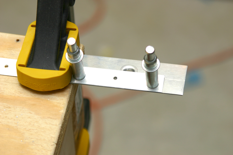 |
The AEX wedge that fits in the trailing edge (hey, that rhymes!) is tricky to countersink. The problem is that it is very thin, so as you countersink the other side of the hole your bit can begin to chatter and screw up your hole. What I did is take a scrap piece of aluminum and drill a hole in it as shown to the left. I clamped this piece under the hole in the wedge to act as a guide for the bit. | |
 |
This is what the final result looks like. The guide hole in the scrap helps to keep the countersink cutter from chattering. | ||
 |
And this is what the wedge looks like after countersinking. Today I also dimpled the rudder skins. | ||
|
3/18/04
(1.5 hrs) |
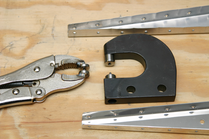 |
Dimpled the lower and upper ribs of the rudder. The last 3 holes in each of these ribs on the trailing end are VERY difficult to dimple with a standard yoke (actually, pretty impossible as the photo shows). I had to break down and buy the vice grip dimple tool from avery tools which worked GREAT for these hard to reach holes. | |
 |
Here I am match drilling the counterweight to the counterweight rib. | ||
 |
Next you countersink the counterweight (see photo), and dimple the holes in the counterweight rib. This will allow the two screws to sit flush with the rib when you get the thing put together. | ||
|
3/19/04
(2 hrs) |
 |
Here are all of the internal pieces of the rudder laid out on the table before priming. | |
 |
And here is everything after priming. | ||
|
3/20/02
(2 hrs) |
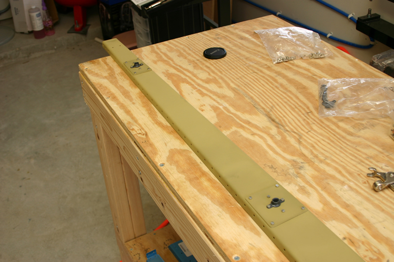 |
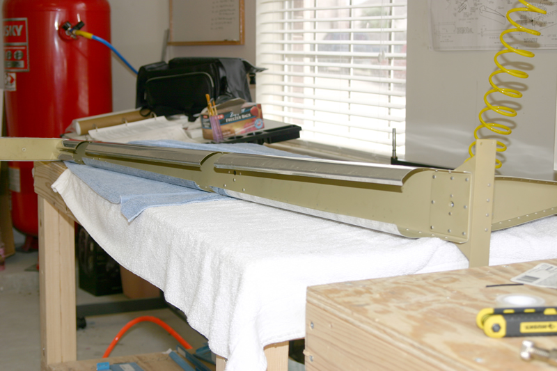
Began riveting the forward spar of the rudder today. Here is a wide angle shot of the spar with the top and middle double plate and platenuts riveted on. Later on the rod end bearings will screw into the platenuts and allow the rudder to swing freely from the Vertical Stabilizer. | |
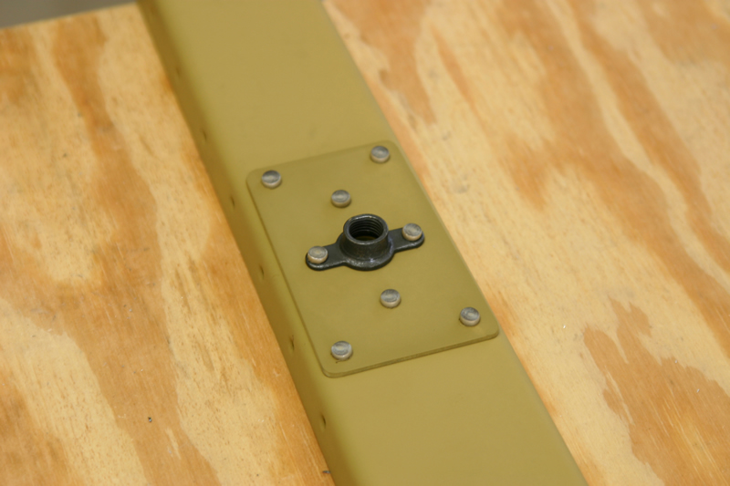 |
Close up of the top doubler plate. | ||
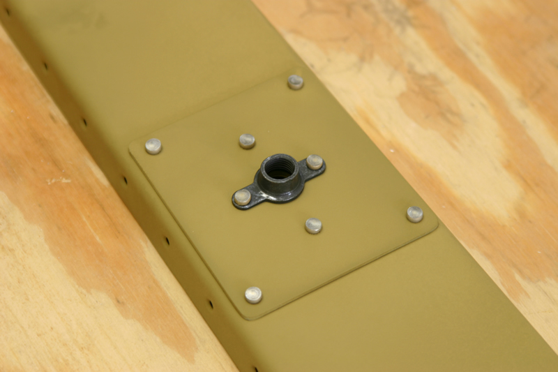 |
Close up of the middle doubler plate. | ||
 |
Next I riveted on the lower rib assembly with the rudder horn and shim. | ||
 |
Side view of lower rib assy. | ||
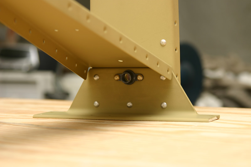 |
Yet another view of the lower rib assy. Note the lower platenut for the lowermost rod end bearing. | ||
|
3/21/02
(1 hrs) |
 |
Here I have riveted on the counterweight rib to the spar. | |
 |
Next I riveted on the counterweight skin to rib *but not the spar!*. Later on the main rudder skin will attach to the spar as well. These rivets were pretty hard to reach because its pretty cramped in there. | ||
|
3/22/02
(2.5 hrs) |
 |
Here I have installed the counterweight. Notice that the screws sit flush with the bottom of the rib. | |
 |
Inside shot of the counterweight. | ||
 |
Here I have one of the skins on and have begun to rivet the counterweight skin and the rudder main skin together. | ||
 |
Here the counterweight skin is riveted to the spar and rudder skin. | ||
 |
I propped up the skin so I could reach inside to set the rivets for the horn brace. | ||
|
3/24/02
(2 hrs) |
 |
Today I riveted all of the skin rivets with the exception of the trailing edge. All of these rivets could be reached by my squeezer and no-hole yoke except for a few on the spar that I had to buck. | |
|
3/25/02
(1.5 hrs) |
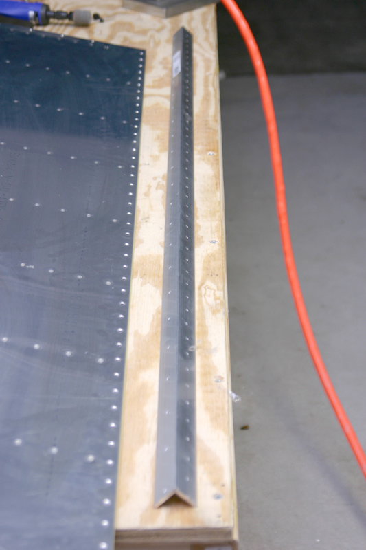 |
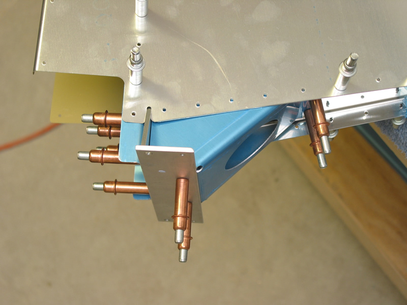
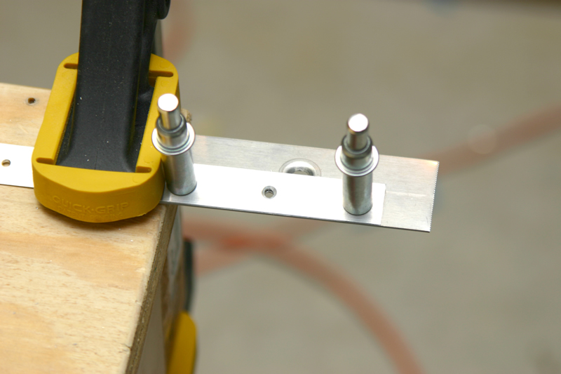
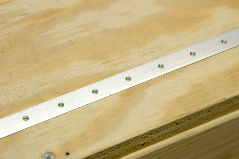
For the trailing edge I deviated from the plans and the results were great. First I drilled two sides of a straight piece of angle. One side was match drilled to every hole in the trailing edge and the other face was drilled to every other hole. | |
 |
Next I bought some metal epoxy from auto zone with a 30min working time, and carefully applied it to the AEX wedge. Next I clecoe'd the assy in every hole and let it cure for 1 day. | ||
|
3/26/02
(1.5 hrs) |
 |
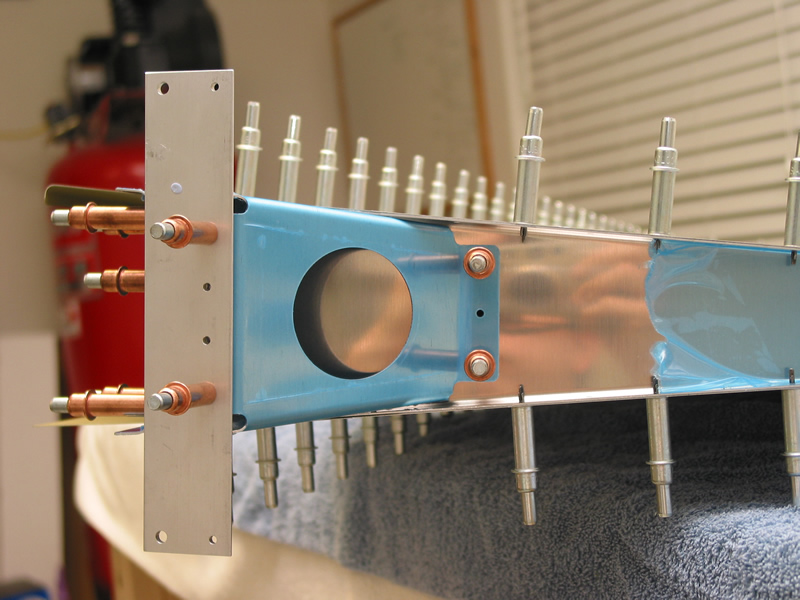
To rivet the TE I put a rivet in every other hole and tapped them in place. | |
 |
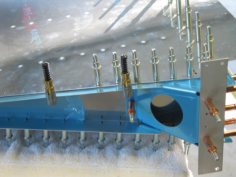
Next I flipped the thing over and cleco'd the assy in every other hole on my trusty angle. In this way the thing is abolutely straight as you rivet. | ||
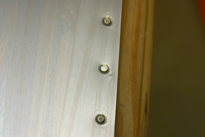 |
I back riveted every other rivet all the way down, then un-cleco'd the assy. I put the remaining rivets in and back riveted them all the way down. I did not use a flush set at all (deviation from plans). My TE is very straight and rigid. Here is a shot of what my double-flush rivets look like. | ||
|
3/28/02
(2 hrs) |
 |
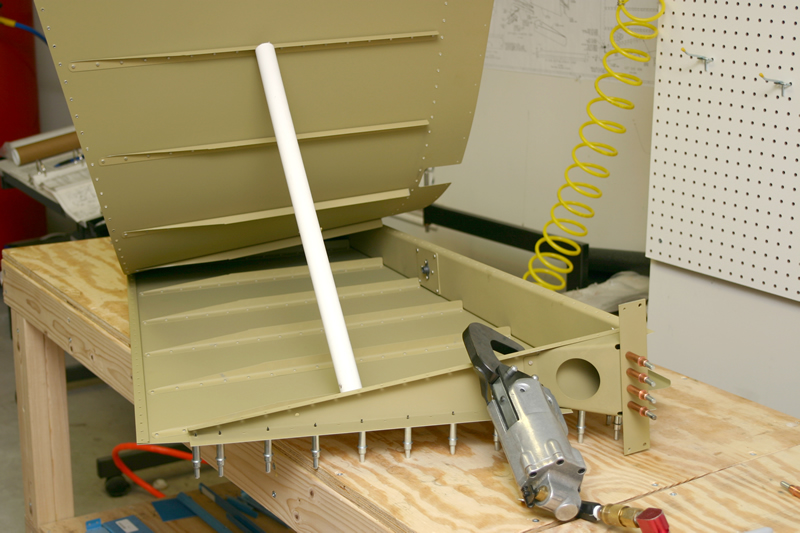
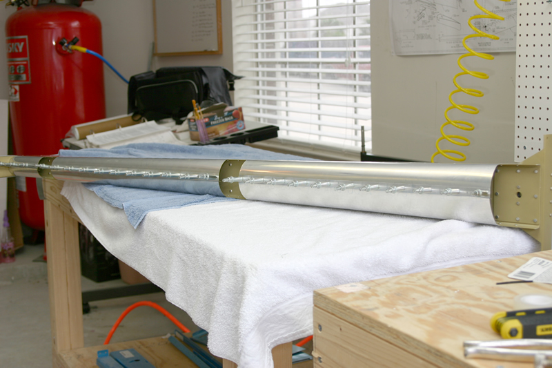
To roll the leading edge of the rudder I duct-tapped a piece of PVC to the leadingedge. | |
 |
After curling the edges using the PVC and vice grips for leverage the leading edge looks like this. | ||
 |
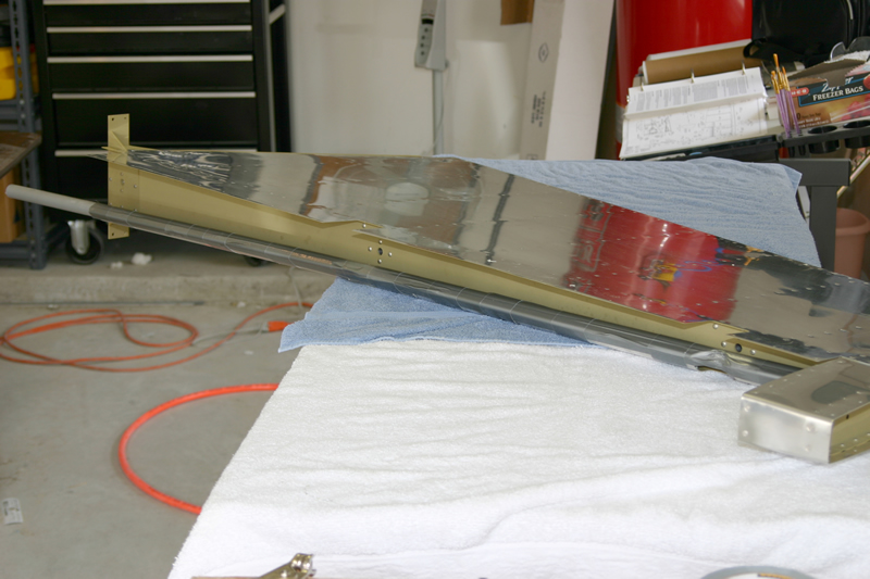
Here it is all cleco'd together ready to be riveted! | ||
 |
The Rudder is Complete! Total time = 43 hours. Man this thing is constructed completely different from the VS and HS. Quite tedious...the elevators will be very similar in construction. | ||