
|
4/02/04
-
|
 |
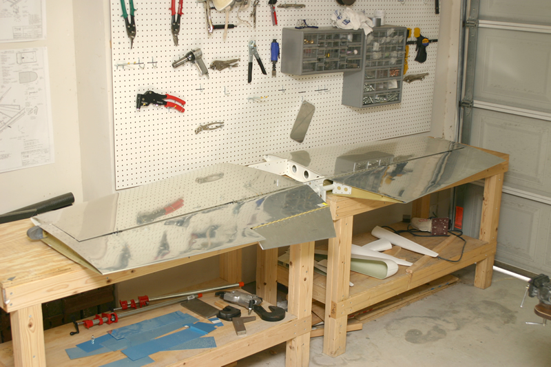
The first
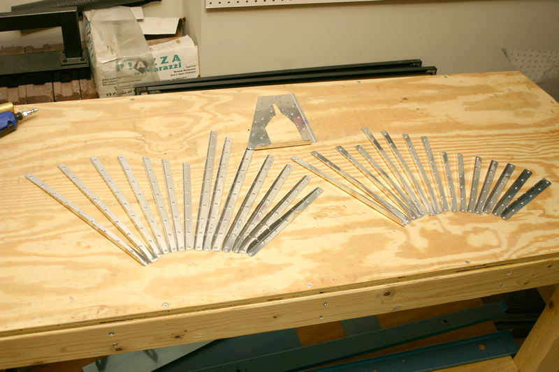
thing you do with the elevators is cut the stiffeners from the aluminum
angle supplied by Vans. The angle has notches in it to help you
know where to cut. After rough cuts with the metal shears, I used
a file and my scotchbrite wheel in the bench grinder to make the
final angle on the stiffeners. Since it's so repetitive, I went
ahead and cut &ground the stiffeners for both elevators. |
|
 |
After
cutting and shaping the elevators stiffeners, here I have cleco'd
and match drilled the stiffeners to the right elevator skin. |
||
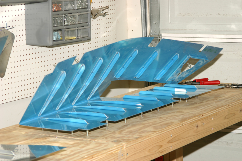 |
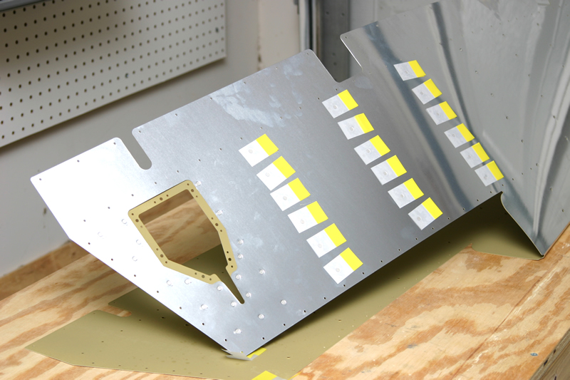
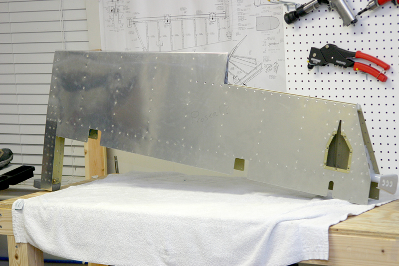
And since I had them handy I went ahead and cleco'd and match drilled the stiffeners to the left elevator skin. Notice the large "missing" piece of the left skin. Later on I will build the elevator trim tab that will be attached to this piece with a hinge. | ||
|
4/02/04
(2 Hrs) |
 |
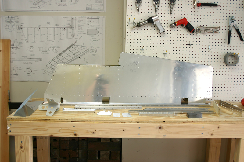
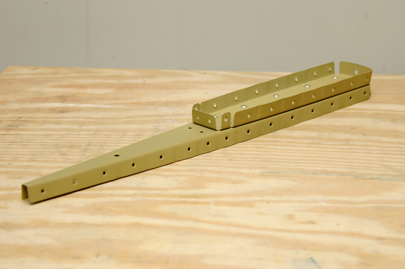
Deburred and dimpled the stiffeners for both elevators. Also deburred and dimpled the trim cable reinforcing place (top of picture) for the left elevator. | |
|
4/06/04
-
4/12/04 (4.5 Hrs) |
 |
Next I dimpled the Left and Right elevator skin using the C-frame tool to accept the flush rivets on the outside of the elevators. I also cleaned up the edges of the aluminum with a deburring tool and scotchbrite wheel. It is important to smooth the edges so that you don't have any stress cracks form down the road. | |
 |
Here is the counterweight assembly for the right elevator. I have clamped the counterweight in the ribs and enlarged the holes to final size. Just after this photo was taken I countersunk the counterweight and dimpled the skin so that the screws will sit flush with the skin surface. | ||
 |
Next I began the process of match drilling the right elevator skeleton together. This is a shot of the spar and the nutplate reinforcing plates being match drilled. Later on the rod-end bearings will screw into the black nutplates to allow the elevator to swing up and down freely. | ||
 |
Next i attached the end rib assembly to the spar and match drilled that attach holes to final size. | ||
 |
And to complete the internal skeleton I cleco'd on the inboard rib of the right elevator (right of picture) and match drilled it to the spar to final size. | ||
|
4/13/04
(2 Hrs) |
No pics to show for it, but I primed the inside of both elevator skins and all of the internal stiffeners. | ||
|
4/16/04
(2 Hrs) |
 |
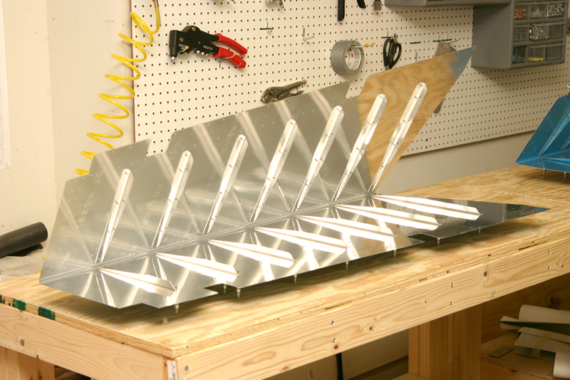
After priming I back riveted the stiffeners to the left and right elevator skins. I ran out of riveters tape and discovered that these little sticky things work great for back riveting and are reusable to boot! | |
 |
Here is the right elevator with stiffeners riveted in place. | ||
 |
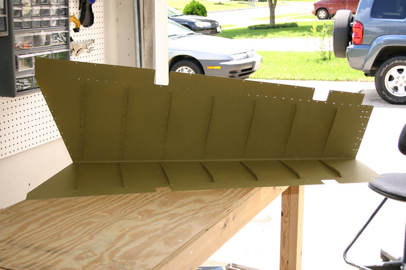
And here is the left elevator skin with stiffeners (and trim cable reinf plate) riveted in place. | ||
|
4/23/04
(2 Hrs) |
 |
Next I began drilling the left elevator skeleton holes to final size. Here is the left elevator forward spar and reinforcing plates being drilled to final size. | |
 |
Here is a close up of the outboard counterbalance ribs on the left elevator being match drilled to final size. | ||
 |
And as before the final part of the elevator skeleton is the inboard most rib which is cleco'd on here for match drilling. Notice that it is a tad shorter than than the right elevator inboard rib. This is to accomodate the trim tab which will be built later. | ||
|
4/24/04
(3 Hrs) |
 |
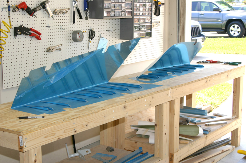
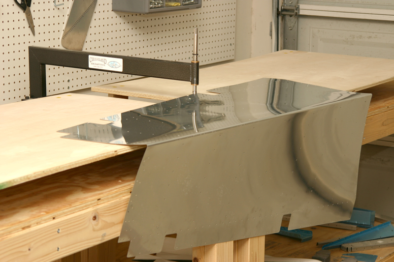
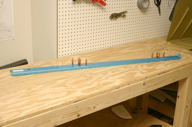
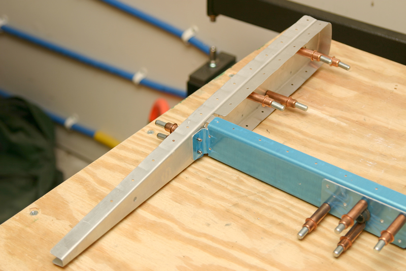
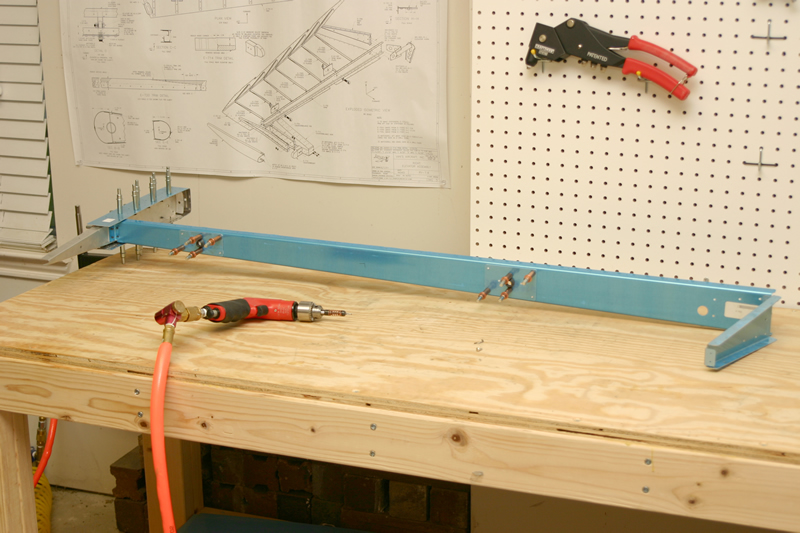
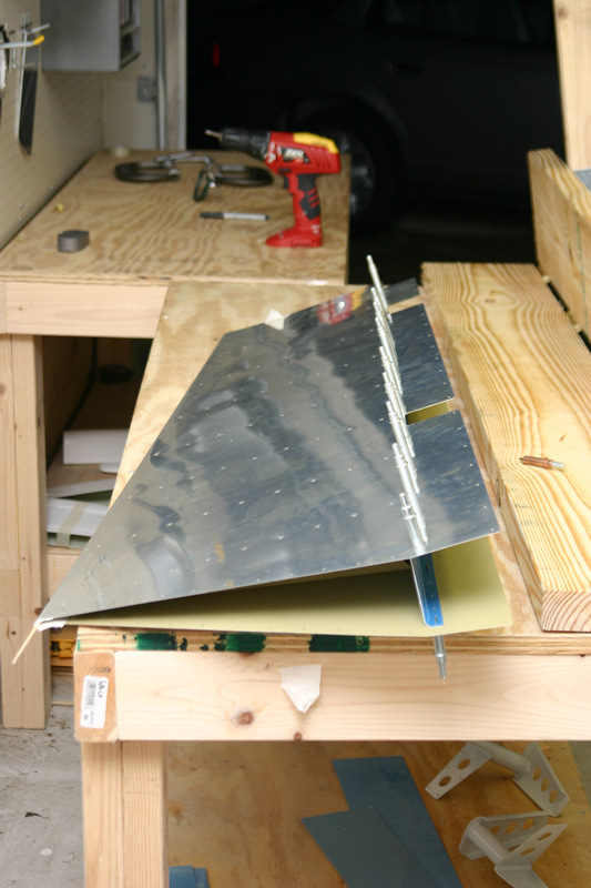
Before you can proceed with building the elevator you need to build a homemade bending brake and bend the skins to the correct size. Here is a pic of the bending brake that I bent. It is pretty much built as the plans call out except that I added the long arms to give me more leverance to push down on the skins. | |
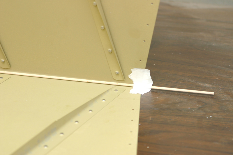 |
Before bending the skins, I tapped an 1/8" dowel rod in the trailing edge to help give a nice radius after bending. It also helps prevent you from "smushing" up the trailing edge. I picked up this trick from the ordnorff construction videos. It worked great! | ||
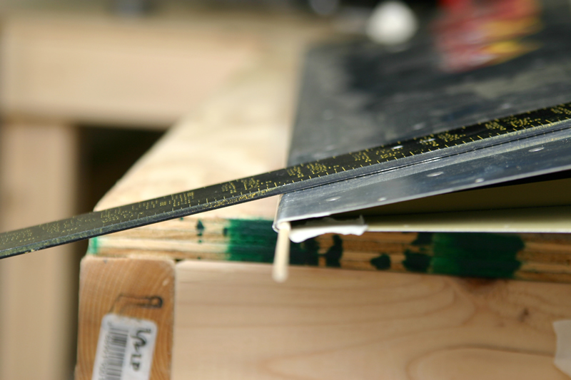 |
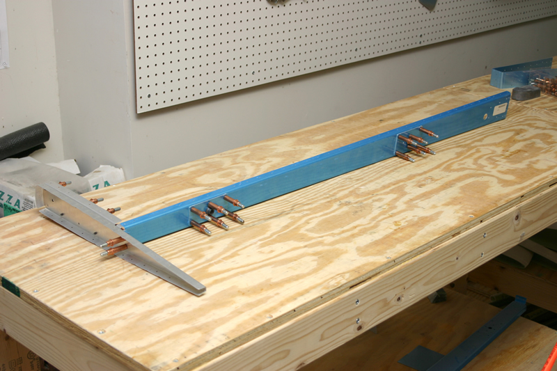
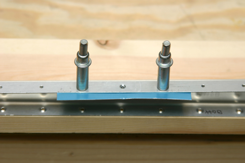
After putting the right elevator skin in the brake and pushing on it carefully, here is a close up of the completed trailing edge. The plans say that a straight edge should lay flat along the skin until the very end of the skin where the radius begins. I was happy with my trailing edges! | ||
 |
And here is the right elevator skin after bending. | ||
 |
And here is the left elevator skin after bending. | ||
 |
Here is a pic of the elevator counterweight after dimpling and countersinking. The screw will fit through the skin and nestle into the countersunk area of the counterweight. | ||
|
4/25/04
(1.5 Hrs) |
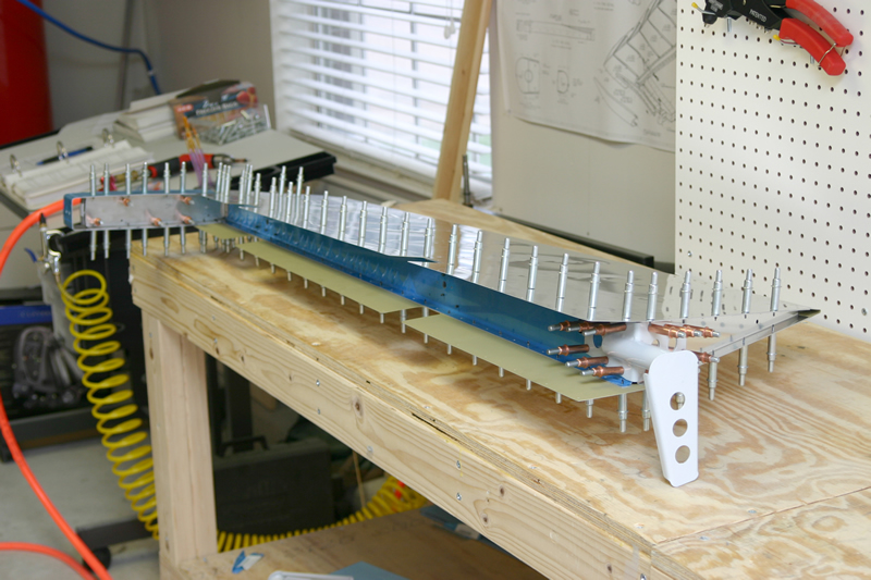 |
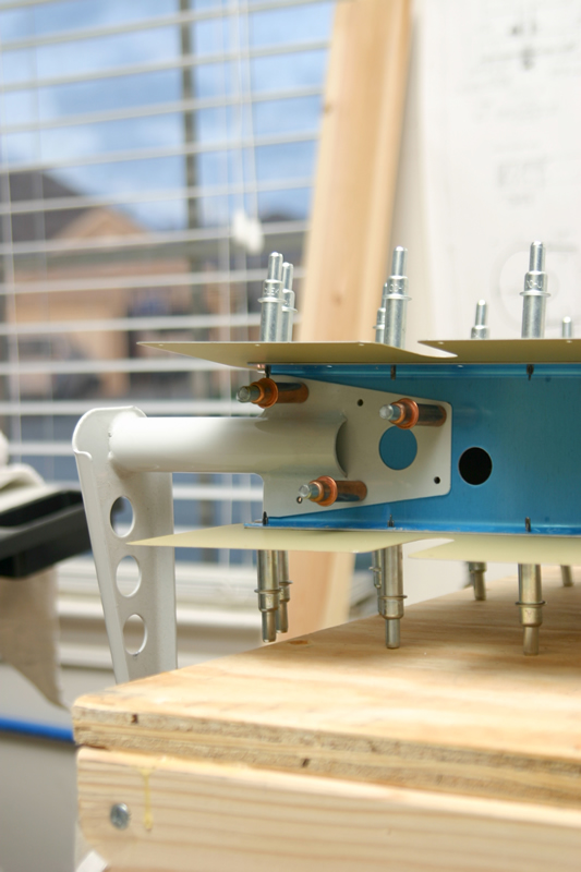
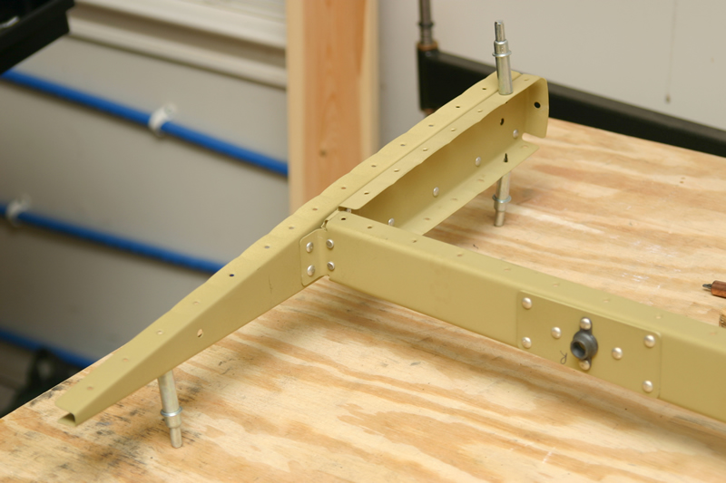
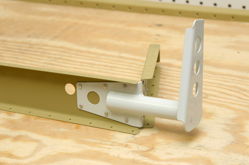
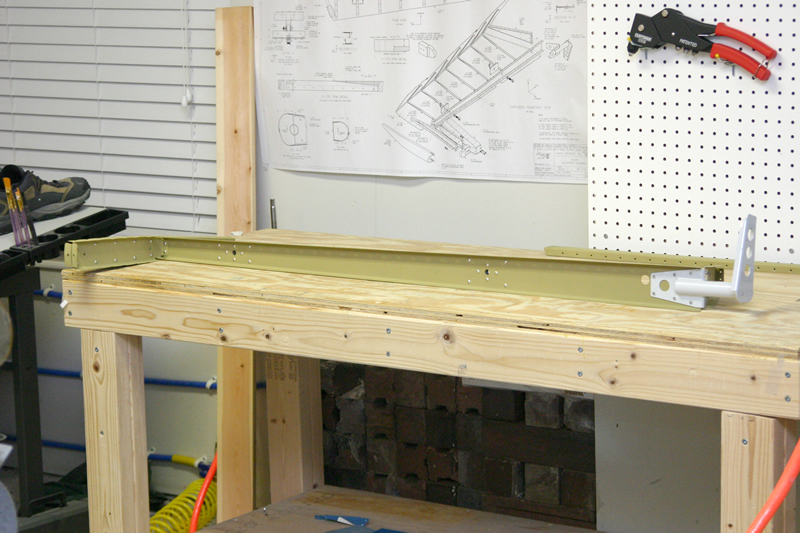
Next I cleco'd the right elevator together and match drilled all of the skin-to-spar/rib holes to final size. I also cleco'd on the elevator horn (white thingy on right side of picture) and match drilled. When I mount the empennage onto the fuselage the pushrods that come from the stick will connect to the white horn here and push the elevators up and down. | |
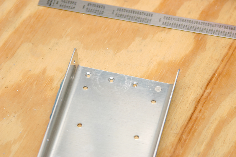 |
Next I uncleco'd the right elevator and countersunk these four holes in the forward spar. Notice that I have a rivet sitting in one of the holes to make sure that I have countersunk far enough. I can be difficult to countersink in thin aluminum like this so I drilled a hole in my workbench and used it as a drill guide for the countersink cutter. These holes need to be countersunk so that when the horn is riveted in place it can lay flat on the spar. | ||
|
5/02/04
(2.5 Hrs) |
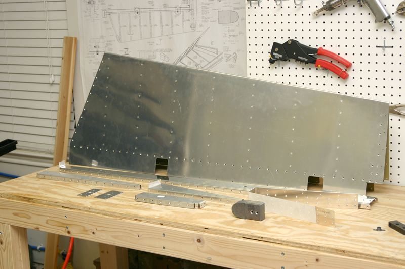 |
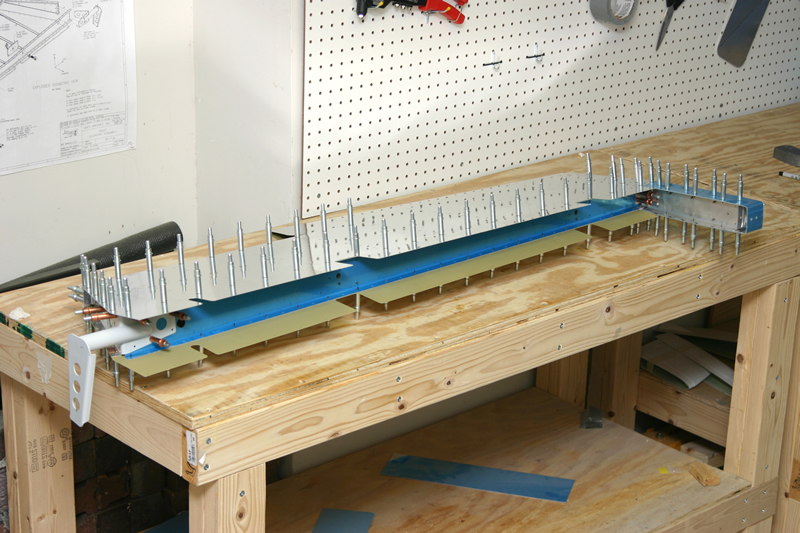
Next I began the arduous process of deburring and dimpling every hole in the right elevator skeleton and skin. here is a shot of the right elevator hardware. Soon I will prime the internal components and rivet this sucker together. Notice the masking tape on the counterbalance skin (right hand of picture). I put this here so that I only prime the part of the skin that tucks into the interior. I didn't want to prime the rest because that part will get painted later on. | |
|
5/06/04
-
5/08/04 (7.5 Hrs) |
 |
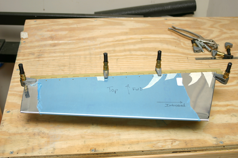
Here is a shot of the Left elevator cleco'd to the skeleton being match drilled to the understructure. | |
 |
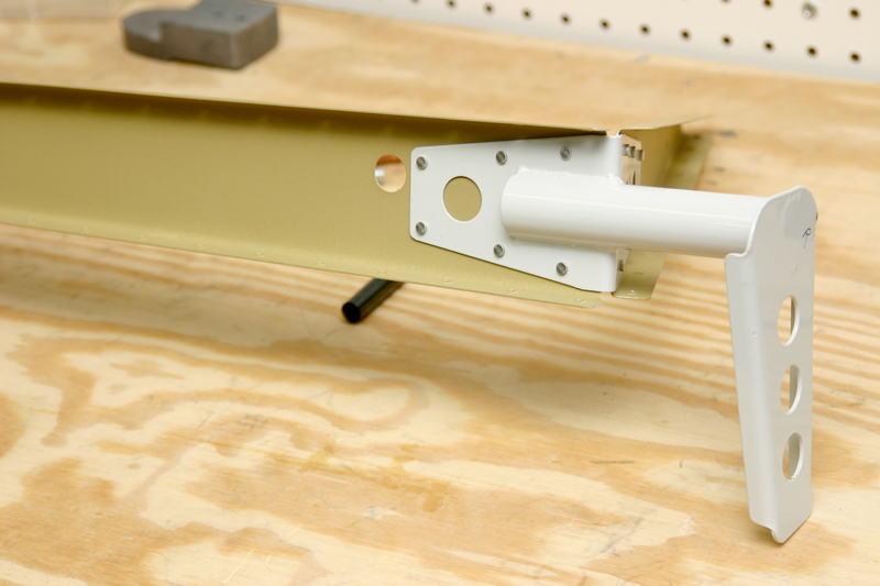
And here is the left elevator horn being match drilled into place. | ||
 |
As with the right elevator, here for forward spar of the left elevator gets some holes countersunk so that the elevator horn can rivet flush up against the spar web. | ||
 |
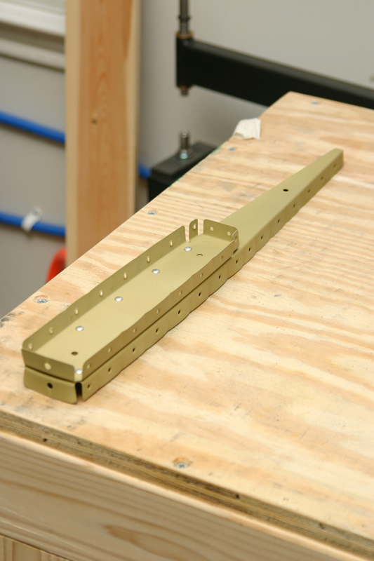
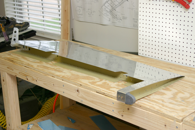
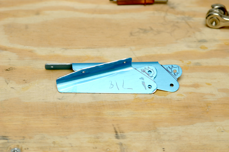
This is the first real difference in the assembly sequence of the left and right elevator. This is the spar that fits in front of the left elevator trim tab to give it some strength. You dimple the bottom holes to accept the rivets, but you have to countersink the top holes. This is to accomodate the hinge itself, which will tuck underneath the flange that I am dimpling here. You drill the hinge, but don't dimple or countersink it. Since the material is pretty thin here I used a scrap piece of aluminum cleco'd underneath the hole to guide the countersink bit. |
||
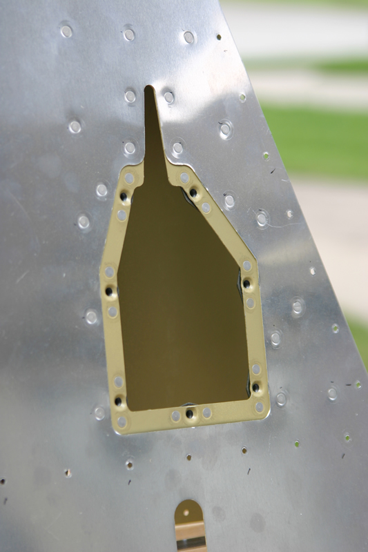 |
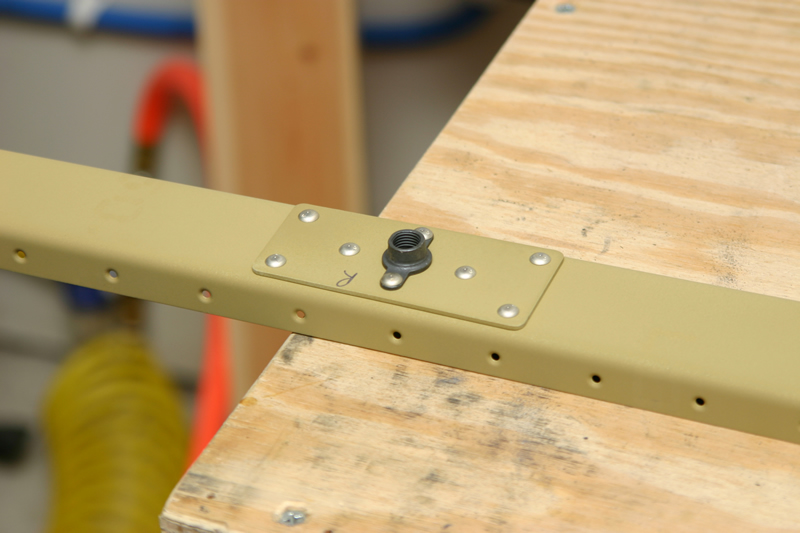
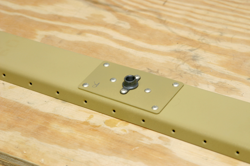
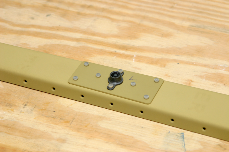
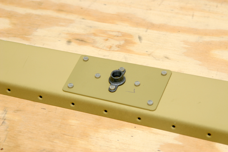
This is the trim cable access plate, and here I have installed the nutplates on the inside of the assembly. During final assembly, the access plate will be secured to these nutplates with flush-head screws. | ||
 |
Next I deburred all of the holes and dimpled the understructure to accept the rivets. here is a shot of all of the left elevator hardware prior to priming. | ||
|
5/11/04
(3.5 Hrs) |
 |
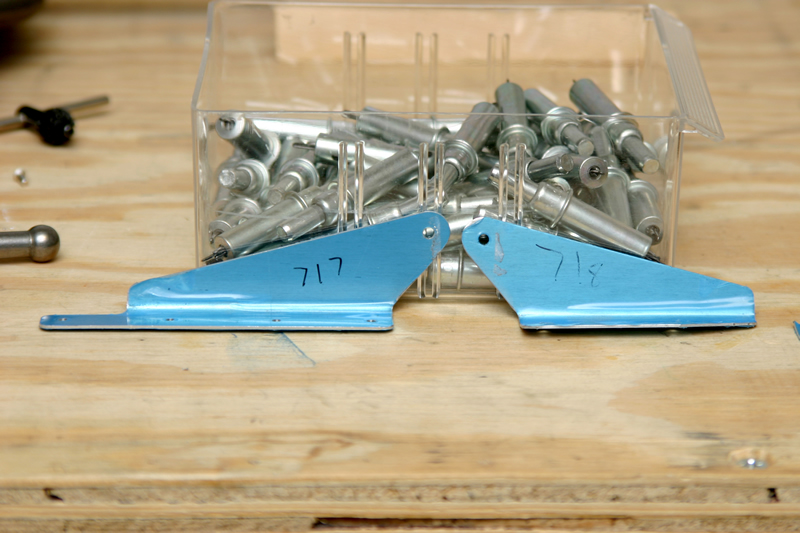
After priming the internal pieces of the skeleton (no pics), I went ahead and cut a chunk out of the right elevator counterweight per the plans. This is done because the elevator trim is on the left elevator and is heavier, so on the right elevator you don't need quite as much of a counterweight to balance the thing. I cut it with a hacksaw then used a file to smooth it out. Wasn't as hard as I thought it would be. | |
 |
Finally get to start riveting the structure together! Here are the outboard ribs for the right elevators. They are riveted together with universal head (round head) rivets. Easy to get with the squeezer. | ||
 |
Here I have riveted one of the reinforcing plates and nutplates onto the right elevator forward spar. | ||
 |
And here is the other reinforcing plates and nutplate riveted onto the right elevator forward spar. | ||
 |
Here I have riveted on the inboard rib onto the right elevator forward spar. Later on I will rivet the pushhorn in this area to move the elevators around with the pushrods. | ||
 |
And here is the outboard rib assembly riveted into place on the forward spar of the right elevator. | ||
 |
And here is the horn riveted into place on the right elevator. Notice that the rivets here are larger to take the control forces from the stick and pushrod. | ||
|
5/12/04
(6 Hrs) |
 |
And here I have riveted the right elevator skin to the skeleton. Using a variety of yokes I was able to reach all of the rivets with my pneumatic squeezer. I believe I used my thin-nose no hole yoke, my longeron yoke, and my big 4" yoke to get them all. Even still I had to put a MK-319BS pop rivet into the very last hole on the trailing edge because my thin nose yoke was too fat to fit in there. | |
 |
Now I began the riveting process all over for the left elevator. For the most part things are the same until you get around the area of the trim tab. Here are the outboard ribs of the left elevator riveted together. | ||
 |
Here is a reinforcing plate and nutplate riveted to the spar of the left elevator. | ||
 |
And here is the other nutplate riveted to the spar of the left elevator. | ||
 |
Here is the inboard rib and horn riveted to the spar on the left elevator. | ||
 |
And here I have riveted on the outboard rib assembly to the left elevator spar. | ||
 |
And as before I have riveted the left elevator skin to the understructure. | ||
|
5/12/04
-
5/15/04 (8 Hrs) |
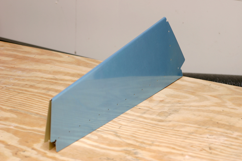 |
Today I started building the trim tab that goes on the left elevator. This little booger is small but challenging to build. Here is a pic of the tab skin after bending it in my brake. | |
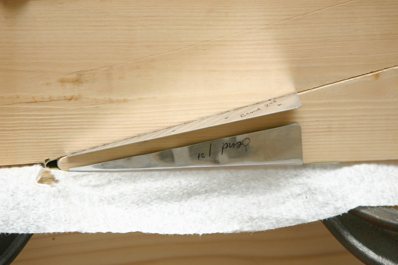 |
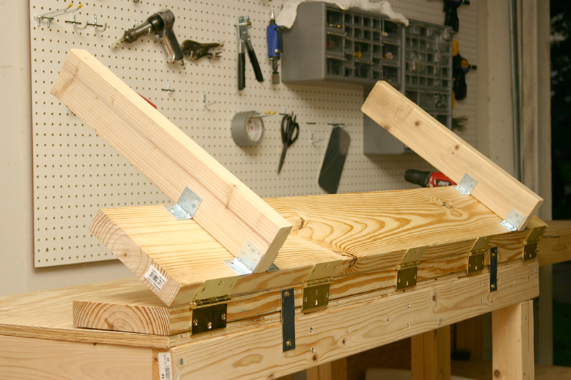
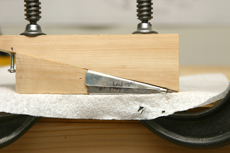
I bent the ends of the tabs using two pieces of wood clamped in a table. You gently use a block of wood and a malet to gently bend it into shape. Notice that you must bend the "bottom" tab first and in sequence so that when it rains no water will get into the tab (it'll just run off). | ||
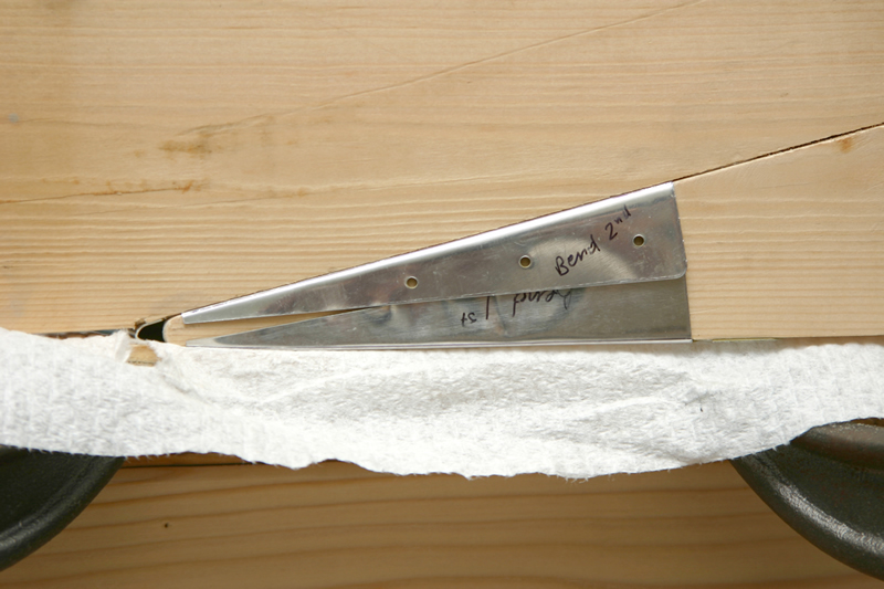 |
And here is the second face bent over the first. In this pic it looks like I really beat the thing up, but it's just the light and reflections. It actually turned out pretty good! | ||
 |
And here is the other side of the tab bent into shape. | ||
 |
Next I matched drilled the small attachments underneath the tab where the cable will connect and (eventually) be able to move the thing up and down. | ||
 |
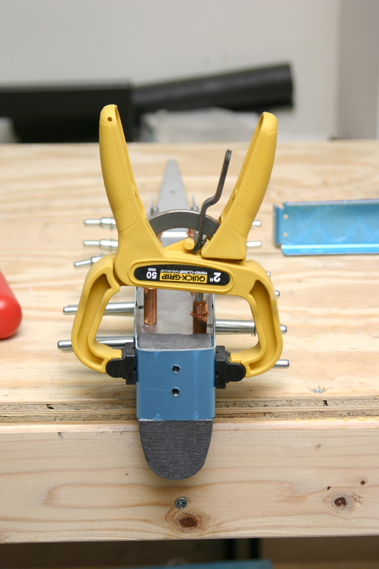
Here I have used the cleco side grip clamps to clamp the hinge into place for match drilling. It is important to line the hinge up perfectly so that it swings up and down without any sideways motion. | ||
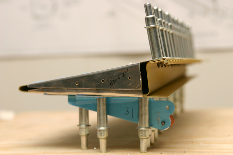 |
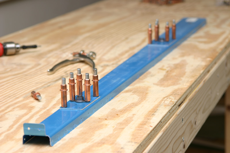
And here is a view along the side of the hinge cleco'd to the tab spar. You can also see a side view of the attachment underneath where the trim cable will attach. Make sure that the hinge is attached UNDERNEATH the spar. | ||
 |
Here I have countersunk the holes in the TOP of the tab spar. The hinge tucks underneath these holes and the hinge is simply drilled (not dimpled or countersunk). The holes in the bottom of the tab spar are dimpled. | ||
 |
I am using the manual trim system (call me old fashioned - but I want a knob!), so you have to trim a little bit off of these pieces so that the trim cable will have enough reach. I have marked the area to remove here. | ||
 |
And here they are after cutting and polishing with a scotchbrite wheel. | ||
 |
Here is a shot of the trim tab attached to the left elevator. Many of these rivets were extremely difficult to get at because its pretty small in there! I did use the MK319BS pop rivet in a few places as a result. | ||
 |
Here is a side view of the tab installed. Later on I will use safety wire to secure the tab hinge but I'll wait for a while to do that (need a longer hinge pin). | ||
|
6/03/04
-
6/04/04 (3 Hrs) |
 |
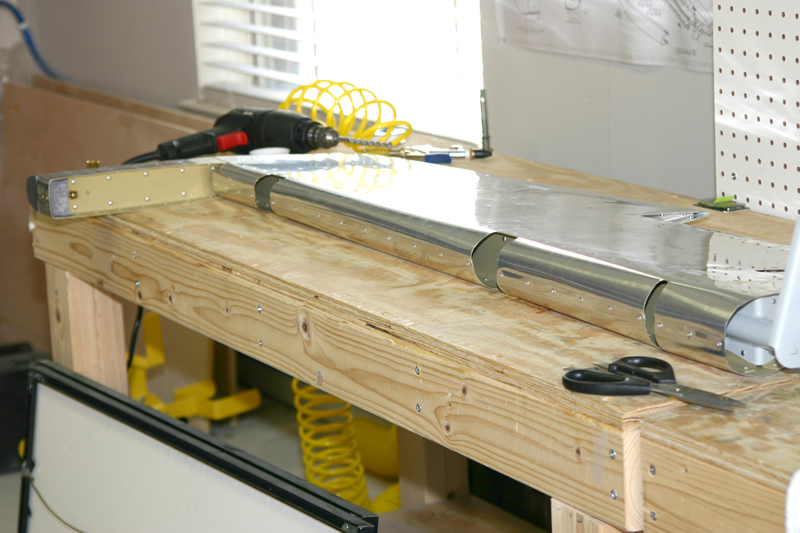
And here I have rolled the leading edge of the right elevator. | |
 |
Here is the left elevator after rolling the leading edge. | ||
|
6/05/04
-
6/15/04 (4 Hrs) |
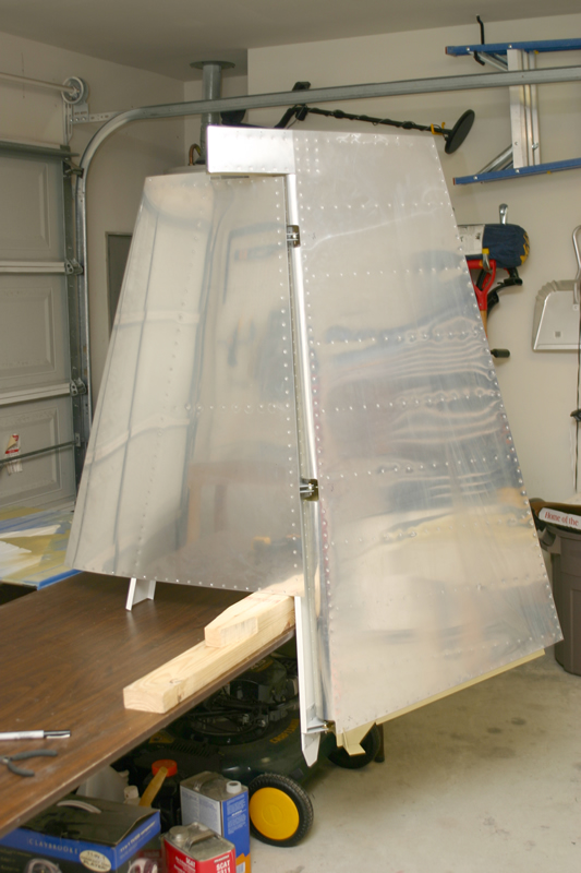 |
And here the VS is attached to the Rudder and fit perfectly! The rudder swings very smooth! Starting to look like an airplane!!! | |
 |
And here are the elevators attached to the HS! | ||
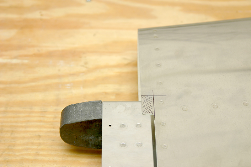 |
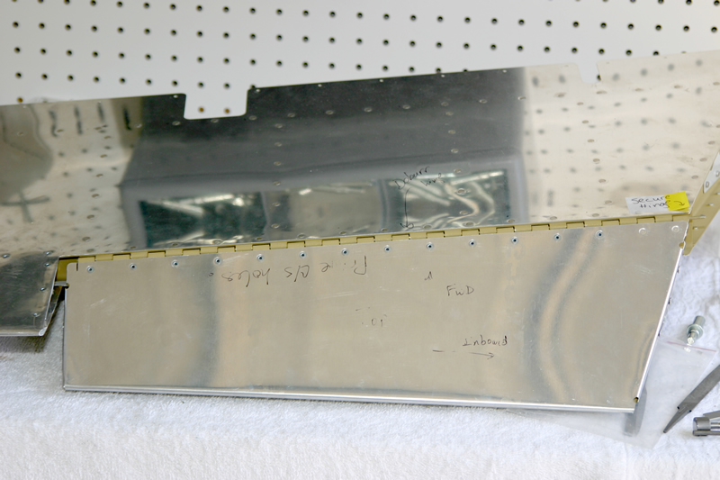
Part of the HS skin needed to be trimmed to allow the elevator to swing. I have marked the place to cut here in this pic. | ||
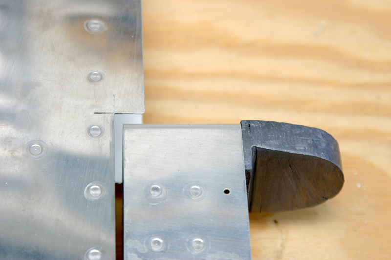 |
After trimming this is what it looks like. I used a dremel, shears, and a file to get to this point. Not too hard. | ||
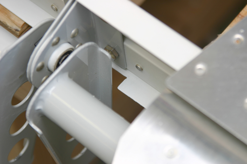 |
Finally, the instructions tell you to take out a chunck of the HS rear spar flange to allow the elevator full clearance of motion. You can see that here. The elevators swing great!!! Total time on the elevators = 58.5 hours. | ||